
Contents
- How Does a Silicon-Carbon Anode Differ From Graphite in Lithium-Ion?
- Why Do Silicon-Carbon Anodes Degrade, and What Lifespan Do Labs Measure?
- How Do Charging Conditions and C-Rates Affect Silicon-Carbon Anodes?
- Is a Silicon-Carbon Battery a Solid-State Battery?
- Checklist for Choosing Silicon-Carbon Versus a Graphite Lithium-Ion Anode
- Frequently Asked Questions
- Does a silicon-carbon battery replace lithium-ion technology?
- Why do different papers quote different silicon capacities and expansion numbers?
- How many years does a smartphone silicon-carbon battery last?
- Does fast charging affect silicon-carbon anodes differently than slow charging?
- Sources
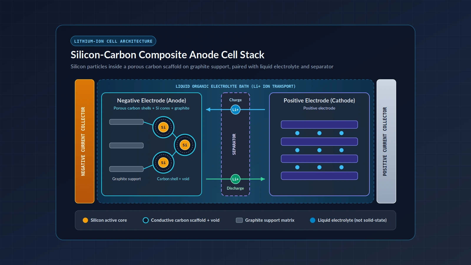
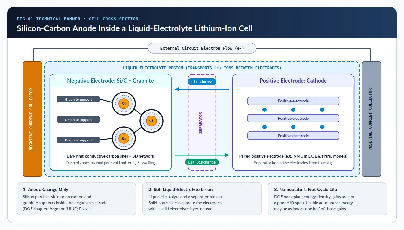
A silicon-carbon battery is a lithium-ion cell whose negative electrode replaces part or all of its conventional graphite with silicon held inside a carbon scaffold or on a graphite support, rather than a solid-state battery. A basic lithium-ion cell contains two electrodes at which redox reactions occur, an electrolyte that transports lithium ions between them, and a separator that prevents the electrodes from touching while allowing ions to move. Commercial cells typically rely on graphite as the negative-electrode active material, and silicon can partially or fully replace that graphite because silicon’s theoretical lithium-storage capacity is about ten times greater than graphite. A commercial smartphone explainer similarly describes a silicon-carbon battery as replacing the graphite anode with a silicon-carbon composite, while the U.S. Department of Energy (DOE) advanced-batteries chapter notes that silicon-based anodes nearing commercialization are primarily silicon or silicon-alloy particles interspersed in, or deposited on, a graphite support, and a Georgia Tech-hosted study describes silicon/carbon composites as a promising next-generation lithium-ion anode class.
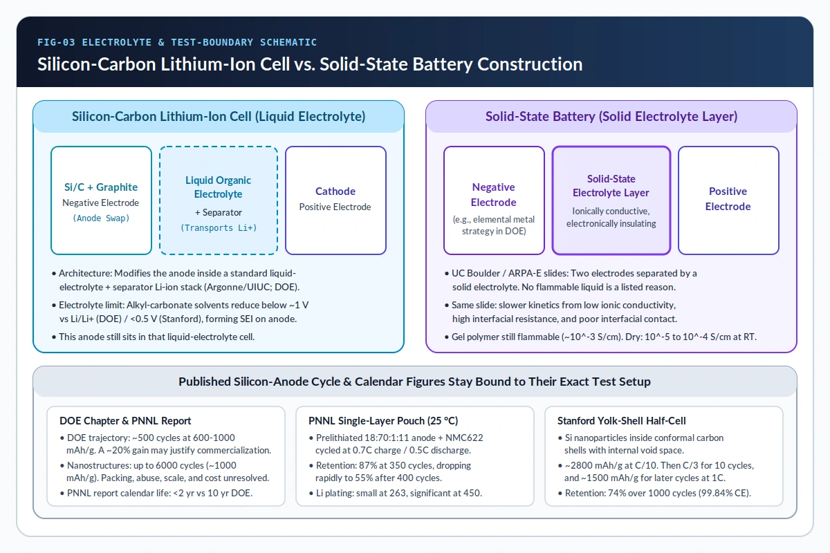
It is not a solid-state battery, and a cell’s nameplate milliamp-hour rating is not its cycle life or calendar lifespan. Solid-state construction separates two electrodes with an electronically insulating solid electrolyte layer. A silicon-carbon anode still sits in a liquid-electrolyte lithium-ion cell, where large volume expansion on lithiation, lost electrical contact, and lithium consumed in the solid-electrolyte interphase (SEI) limit cyclability. The DOE chapter’s cell model reports nameplate energy-density gains of 27% at 1000 mAh/g and 37% at 2000 mAh/g, and it says usable energy in automotive applications may be as low as one half of those nameplate values because of depth-of-discharge limits. A launch statement that a silicon-carbon battery “supports all-day endurance” does not define the screen, network, or recording load. Anode comparisons of this kind sit with the other Android phone buying guides.
How Does a Silicon-Carbon Anode Differ From Graphite in Lithium-Ion?
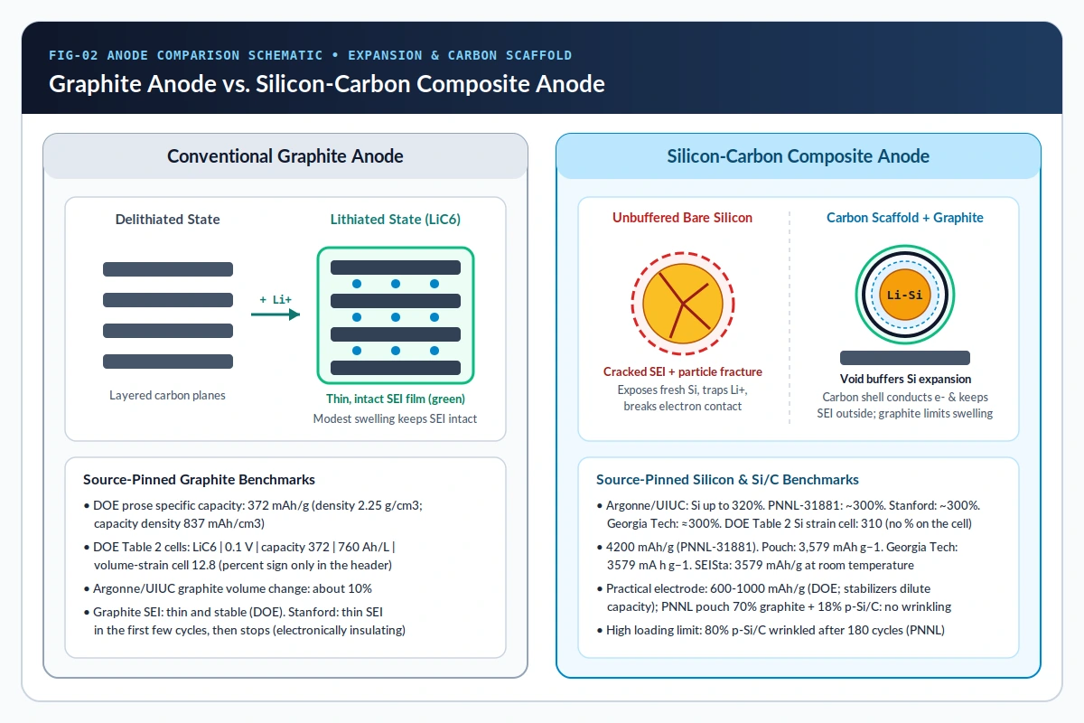
Graphite’s specific capacity is 372 mAh/g, and a crystallographic density of 2.25 g/cm3 limits its capacity density to 837 mAh/cm3. Graphite enabled modern lithium-ion batteries by replacing lithium metal, which has safety and life issues associated with lithium dendrite formation during cycling, without sacrificing much operating voltage. Alternative anodes based on silicon and tin provide theoretical specific capacities and capacity densities up to a factor of 10 higher than graphite. The Argonne National Laboratory and University of Illinois manuscript states that silicon’s theoretical lithium-storage capacity is about ten times that of graphite, and it reports volume changes up to 320% in silicon particles against about a 10% volume change for graphite. Every other capacity and expansion figure stays with the paper that printed it.
The DOE chapter says even currently attainable capacities remain well short of the theoretical limits. Supporting an active alloy with an inactive stabilizing matrix improves cycle life, though it dilutes overall electrode capacity. In the DOE chapter, silicon anodes with reversible specific capacities of 600 to 1000 mAh/g appear close to commercial implementation. Across laboratory studies, carbon serves several structural roles: milled ~150 nm silicon powders coated with a thin carbonaceous layer in an Argonne National Laboratory and University of Illinois accepted manuscript (DOI 10.1116/1.5130764, whose copyedited version of record will differ) are blended with carbon black for electronic conduction, graphite to limit overall electrode expansion, and partially lithiated polyacrylic acid (Li-PAA) as a binder.
Other research architectures buffer expansion through internal void space and porous carbon networks rather than relying on graphite alone:
- Nanosized silicon-carbon architectures: A Pacific Northwest National Laboratory (PNNL) pouch-cell study groups nanosized silicon with carbon into nanoparticle or nanotube structures, nanoporous silicon/carbon structures, and core-shell designs.
- Pitch-coated porous silicon: That same PNNL paper investigates micron-sized nanoporous silicon coated with pitch-derived carbon (written p-Si/C, containing about 60% pure silicon), combining nanosized silicon primary particles, internal porosity to accommodate expansion, and a three-dimensional conductive carbon network.
- Pore-sealing carbon shells: The PNNL-31881 technical report explains that porous silicon voids act as a buffer zone for volume change, while carbon coatings limit surface diffusion during carbonization to preserve porosity and can block surface pores so liquid electrolyte stays out of the interior.
- Surface-oxide and carbon coatings: A Georgia Tech-hosted study examines 1 to 10 nm surface oxide layers on silicon nanoparticles, finding ~5 nm optimal on its composite and noting that a carbon coating reduces electrolyte side reactions while raising electrical conductivity.
Every capacity, energy-density, and volume-expansion number in battery research depends on the specific electrode recipe, active-mass definition, and source paper. The table below keeps each benchmark pinned to its exact document:
Scroll horizontally to view all table columns.
| Source Document | Anode or Cell Basis | Specific Capacity or Energy Metric | Volume Change or Strain Metric | Scope Note in Source |
|---|---|---|---|---|
| DOE Chapter Prose | Graphite negative electrode | 372 mAh/g; 837 mAh/cm3 at 2.25 g/cm3 | Not stated in this prose passage | Higher specific capacity than paired cathodes |
| DOE Table 2 (Graphite) | Limiting composition LiC6 at 0.1 V | Specific capacity cell 372; capacity density cell 760 Ah/L | Volume-strain cell 12.8 | Percent symbol is in column header, not attached to 12.8 |
| DOE Table 2 (Silicon) | Limiting composition Li4.4Si at ~0.3 V | Up to 10x graphite in prose; Table 2 cell uses a thousands separator | Volume-strain cell 310 | Percent symbol is in column header, not attached to 310 |
| DOE Chapter Practical & Model | Graphite-supported silicon or silicon-alloy particles; NMC cathode; electrode thickness up to 100 µm | 600–1000 mAh/g close to commercial implementation; nameplate gains of 27% at 1000 mAh/g and 37% at 2000 mAh/g | Not stated in this model summary | Those gains are nameplate values; usable automotive energy may be as low as one half of them |
| Argonne / UIUC Manuscript | Milled ~150 nm Si/C, graphite, carbon black, Li-PAA | Capacities include Si, graphite, and carbon black mass | Up to 320% for Si particles vs ~10% for graphite | Lithium-metal coin half-cells fabricated at Argonne CAMP |
| PNNL-31881 Report | Silicon vs graphite theoretical comparison | 4200 mAh/g theoretical (10x graphite) | ~300% during lithiation and delithiation | Theoretical silicon benchmark in this report |
| PNNL Pouch Paper | Micron p-Si/C (~60% pure Si) + graphite | 3,579 mAh g−1 theoretical (~10x graphite) | Accommodated by internal porosity; 80% p-Si/C wrinkled | Single-layer NMC622 pouch cell at 25 °C |
| Stanford Yolk-Shell Paper | Yolk-shell Si nanoparticles in carbon shells | >3500 mAh/g initial experimental (10x graphite); ~2800 mAh/g at C/10 | ~300% for silicon | Designed nanostructured half-cell electrode |
| Georgia Tech-Hosted Paper | Carbon-coated Si nanoparticles with ~5 nm oxide | 3579 mA h g−1 theoretical | ≈300% during lithiation and delithiation | Nanocomposite electrode modeling and testing |
| SEISta Quarterly Note | Room-temperature silicon thin-film analysis | 3579 mAh/g theoretical room-temperature capacity | Not stated in this capacity note | Values above 3579 mAh/g reflected substrate-lithiation active-mass error |
Why Do Silicon-Carbon Anodes Degrade, and What Lifespan Do Labs Measure?
Silicon-carbon anodes degrade primarily because repeated expansion cracks the solid-electrolyte interphase (SEI), exposing fresh silicon that consumes active lithium and electrolyte solvent while disconnecting particles from the conductive network. Because lithium insertion and extraction sit below 0.5 V versus Li+/Li in the Stanford study and alkyl-carbonate electrolytes reduce below ~1 V versus Li/Li+ in the DOE chapter, organic electrolyte decomposes on the anode surface to form an SEI layer. On graphite, a thin passivating SEI forms in the first few cycles and stops growing because the layer is electronically insulating. On alloy anodes such as silicon, massive volume swings fracture that passivation film, continually exposing bare silicon that traps lithium ions in new SEI growth and parasitic side reactions.
Laboratory coin-cell and pouch-cell experiments show how strongly binder conductivity, graphite blending, and surface exposure alter that degradation:
- Electronic percolation and first-cycle efficiency: In Argonne/UIUC coin half-cells (10 wt% FEC in 1.2M LiPF6 in EC:EMC 3:7 by weight, cycled between 1.0 and 0.1 V at ~C/25 and 30 °C), the 15Si/C cell has the lowest capacity and the highest coulombic efficiency because that electrode has the lowest silicon content. By contrast, the 90Si/C composition has the lowest coulombic efficiency, which the manuscript says may be silicon particles disconnecting from the electron network after the initial lithiation, and unlike the others this electrode does not contain carbon black; the 1.0 to 1.1 V differential-capacity peak characteristic of FEC reduction is absent for 90Si/C, and the manuscript postulates that capacity differences among the 70Si/C coatings arise from differences in the solid electrolyte interphase.
- Open-circuit leak reactions and calendar life: PNNL-31881 observes that in most literature where nano silicon is deposited on graphite, the silicon remains exposed to electrolyte with a large surface area, and carbon-coated silicon monoxide (SiO) typically exhibits first-cycle efficiency below 75%. According to that report, silicon or SiO will keep reacting with the electrolyte, chemically or electrochemically through leak current, even at open circuit, and the authors believe that is the origin of shortened calendar life, while to date all silicon-based lithium-ion batteries developed by industry still have a calendar lifetime of less than two years, far less than the 10 year target required by DOE.
- Electrode wrinkling and swelling: The PNNL pouch paper confirms that silicon deposited on porous graphite accelerates fading and shortens calendar life during cycling and storage. In single-layer pouch cells, an anode with 80% p-Si/C was severely wrinkled after 180 cycles, while the anode with 70% graphite and 18% p-Si/C shows no wrinkling, and the paper says the 80% p-Si/C loading used in coin cells may not be practical for large pouch cells because the SEI grows continuously over many cycles, which leads to high end-of-life swelling; that graphite-blended pouch anode used a weight ratio of 18:70:1:11 for p-Si/C, graphite, carbon black, and PI binder, with active-material loading of about 5.04 mg cm−2.
Published cycle counts stay tied to the specific cell format and test protocol rather than translating directly into smartphone years:
Scroll horizontally to view all table columns.
| Study or Report | Test Cell & Formulation | Cycle Count & Retention | Efficiency & End-of-Life Behavior |
|---|---|---|---|
| DOE Chapter Trajectory | Commercial insertion model (600–1000 mAh/g) | About 500 cycles | Consumer-electronics trajectory; a marginal energy-density improvement of about 20% over graphite-based lithium ion may be enough to justify commercialization |
| DOE Nanostructure Literature | Nanostructured alloy anodes (~1000 mAh/g) | Up to 6000 cycles demonstrated | Volume packing density, reactivity under abuse scenarios, manufacturing scalability, and cost are not yet resolved |
| PNNL Single-Layer Pouch | In that single-layer pouch anode the weight ratio of p-Si/C, graphite, carbon black, and PI binder was 18:70:1:11, and those pouch and coin cells were tested at 25 °C | 87% retention at 350 cycles; 55% at 400 cycles | 90.89% first-cycle CE; 99.91% CE after 20 cycles; 99.92% average CE after 350 cycles |
| Stanford Yolk-Shell Cell | Yolk-shell Si inside conformal carbon shells with voids | 1000 cycles with 74% retention | 99.84% coulombic efficiency; ~2800 mAh/g at C/10 |
These laboratory and government reports do not state a smartphone silicon-carbon lifespan in years. The DOE chapter’s about 500 cycles is a consumer-electronics development trajectory at 600-1000 mAh/g, and the chapter says a marginal energy-density improvement of about 20% over graphite-based lithium ion may be enough to justify commercialization; the PNNL pouch result of 87% after 350 cycles and 55% after 400 cycles is one single-layer cell at 25 °C, and PNNL-31881’s calendar lifetime of less than two years is that report’s statement about industry silicon cells versus a 10 year target required by DOE, not a phone warranty. If an Android handset loses charge unusually quickly between plugs or while warm, Android Help notes that battery drain accelerates sharply when a phone is hot—even when idle—and that thermal drain can damage the cell; step-by-step software and thermal checks belong in our guide to fixing Android battery drain.
How Do Charging Conditions and C-Rates Affect Silicon-Carbon Anodes?
Charging speed and voltage boundaries govern silicon-carbon longevity through phase preservation, rate-dependent capacity drop, and metallic lithium plating. In the DOE chapter, electrochemical lithiation forms a metastable amorphous lithium-silicon (Li-Si) alloy rather than equilibrium crystalline intermetallic phases, and cycling inside a limited capacity and potential window that preserves that amorphous phase extends cycle life. That electrochemical boundary is a cell-design operating window, not a phone menu setting, and no saved source states a phone state-of-charge cap.
Higher charge and discharge C-rates also compress deliverable capacity and introduce plating risk in laboratory silicon-carbon cells. In the Stanford yolk-shell study, cells cycled once at C/10, for 10 cycles at C/3, and then at 1C stabilized near 1500 mAh/g at 1C compared with about 2800 mAh/g at C/10. In the PNNL single-layer pouch study, where 1C means the full capacity can be discharged in one hour, discharge rate performance is 92% (172 mAh g−1) at 1C when normalized to 188 mAh g−1 at 0.1C. During long-term cycling at 0.7C charge and 0.5C discharge after a 0.1C formation cycle, postmortem inspection found a small amount of lithium plating on the p-Si/C anode after 263 cycles and a significant amount after 450 cycles, and the paper says that plating is one reason capacity fading occurs, while a stable electrode structure is critical to avoid disintegration of the anode structural integrity and lithium plating.
PPS and fixed-PDO descriptions are charger-side requests, and the phone manages battery charging internally. Adapter and cable checks stay in the USB-C PD PPS versus fixed PDO charging negotiation guide. Pause USB PD charging when gaming pauses battery charging and prioritizes power to the device while gaming; that power-path check stays in the Android bypass charging power path and heat guide.
Is a Silicon-Carbon Battery a Solid-State Battery?
No: a silicon-carbon battery modifies the negative electrode inside a standard liquid-electrolyte lithium-ion cell, whereas a solid-state battery replaces the liquid electrolyte and porous separator with a solid electrolyte layer. Across the DOE chapter, the Argonne/UIUC manuscript, and the Stanford report, silicon-carbon anodes operate in liquid organic carbonate electrolytes alongside a porous separator. By contrast, the DOE chapter groups inorganic, organic, and composite solid electrolytes as strategies aimed at enabling elemental metal negative electrodes, and ARPA-E Crash-Safe Energy Storage Systems workshop slides from Sehee Lee at the University of Colorado at Boulder define solid-state construction as two electrodes separated by an electronically insulating, ionically conductive solid-state electrolyte layer.
Those UC Boulder slides list no flammable liquid electrolyte as a reason for a solid-state battery, and the same slide lists slower kinetics from low ionic conductivity, high interfacial resistance, and poor interfacial contact. The same slides keep the polymer categories separate: a gel polymer electrolyte is still flammable, with poor mechanical properties and conductivity of about 10-3 S/cm, while a dry polymer electrolyte has low ionic conductivity of 10-5 to 10-4 S/cm at room temperature. The DOE chapter says many inorganic solid electrolyte compositions have been investigated since the 1970s, and their broad challenges are limited room-temperature conductivities and inadequate chemical stability at the anode or the cathode.
Checklist for Choosing Silicon-Carbon Versus a Graphite Lithium-Ion Anode
Use this verification checklist when comparing smartphone battery claims or technical briefs without relying on marketing shorthand:
- Verify what changed in the cell: Confirm whether the anode uses silicon particles inside a carbon scaffold or graphite matrix inside a liquid-electrolyte lithium-ion cell rather than assuming solid-state electrolyte chemistry.
- Pin expansion and capacity figures to their exact paper: Keep graphite’s 372 mAh/g capacity and DOE Table 2 strain cells (12.8 for graphite, 310 for silicon, percent sign only in the column header) separate from Argonne’s up to 320% for silicon versus about 10% for graphite, PNNL-31881’s 4200 mAh/g and about 300%, the pouch paper’s 3,579 mAh g−1, Georgia Tech’s 3579 mA h g−1, and SEISta’s room-temperature 3579 mAh/g.
- Check the test format and charging rate behind cycle claims: Separate the DOE chapter’s about 500 cycles for consumer electronics from the PNNL single-layer pouch cell, which kept 87% after 350 cycles and 55% after 400 cycles, while those pouch and coin cells were tested at 25 °C in that paper. Long-term cycling of those full cells was 0.7C charge and 0.5C discharge after a formation cycle. The Stanford yolk-shell report states about 2800 mAh/g at C/10, 1000 cycles with 74% capacity retention, and about 1500 mAh/g for later cycles at 1C.
- Separate battery chemistry from device charging and heat management: Confirm adapter compatibility via USB-C PD/PPS rules, route gaming power-path questions to bypass charging, and inspect thermal drain separately from anode materials.
- Treat endurance slogans as load-dependent: Note that launch statements claiming all-day endurance do not specify screen brightness, cellular radio activity, or camera recording load.
Frequently Asked Questions
Does a silicon-carbon battery replace lithium-ion technology?
No. A silicon-carbon battery is a lithium-ion cell in which silicon or a silicon-carbon composite replaces part or all of the graphite in the negative electrode while retaining a cathode, porous separator, and liquid organic electrolyte.
Why do different papers quote different silicon capacities and expansion numbers?
Authors report different reference definitions: DOE chapter prose cites 600–1000 mAh/g for near-commercial silicon electrodes, PNNL-31881 quotes 4200 mAh/g theoretical capacity and about 300% expansion, Argonne/UIUC cites up to 320% silicon expansion versus about 10% for graphite, the pouch paper prints 3,579 mAh g−1, Georgia Tech prints 3579 mA h g−1, and SEISta prints 3579 mAh/g as the theoretical capacity achievable at room temperature.
How many years does a smartphone silicon-carbon battery last?
None of the laboratory or government battery reports reviewed here publish a smartphone lifespan in years. Published metrics describe modeled consumer-electronics trajectories (~500 cycles in DOE), single-cell laboratory tests (such as PNNL’s 87% retention at 350 cycles and 55% at 400 cycles, with those pouch and coin cells tested at 25 °C), and a calendar lifetime of less than two years for silicon-based lithium-ion batteries developed by industry, far less than the 10 year target required by DOE, in PNNL-31881.
Does fast charging affect silicon-carbon anodes differently than slow charging?
Laboratory data show clear rate sensitivity and potential-window effects: preserving the metastable amorphous Li-Si phase within a limited capacity and potential range extends cycle life in DOE guidance, Stanford’s yolk-shell electrode dropped from ~2800 mAh/g at C/10 to ~1500 mAh/g at 1C, and PNNL pouch cells charged at 0.7C developed lithium plating after 263 and 450 cycles.
Sources
- U.S. Department of Energy (DOE), Chapter 17: Advanced Batteries (2022) — Graphite, tin, and silicon Table 2 metrics, SEI reduction behavior, amorphous Li-Si cycling window, 600–1000 mAh/g commercial trajectory, nameplate cell model gains, and inorganic solid-electrolyte challenges.
- Argonne National Laboratory and University of Illinois accepted manuscript and DOI 10.1116/1.5130764 — Lithium-ion cell structure, volume changes up to 320% in silicon particles versus about 10% for graphite, milled silicon particles of about 150 nm with a carbonaceous coating, and coin half-cells with 10 wt% FEC at 30 °C cycled at about a C/25 rate.
- Pacific Northwest National Laboratory (PNNL), Report PNNL-31881 — 4200 mAh/g and ~300% theoretical benchmarks, <75% carbon-coated SiO first-cycle efficiency, open-circuit leak reactions, sub-two-year industry calendar life vs 10 year DOE target, and porous Si carbon coating mechanisms.
- Pacific Northwest National Laboratory porous silicon/carbon pouch-cell study — theoretical capacity 3,579 mAh g−1, pitch-coated micron-sized porous silicon/carbon with about 60% silicon. In that single-layer pouch anode the weight ratio of p-Si/C, graphite, carbon black, and PI binder was 18:70:1:11, and those pouch and coin cells were tested at 25 °C. Retention was 87% after 350 cycles and 55% after 400 cycles. An anode with 80% p-Si/C was severely wrinkled after 180 cycles, with lithium plating after 263 cycles and again after 450 cycles.
- Sandia National Laboratories and University of Colorado Boulder SEISta quarterly note — 3579 mAh/g is the theoretical capacity achievable at room temperature, and coin-cell values above 3579 mAh/g were an artifact of lithiating the underlying silicon substrate.
- Stanford University (Cui Group), Yolk-Shell Silicon-Carbon Electrode (Nano Letters, 2012) — >3500 mAh/g initial capacity, ~300% expansion, <0.5 V organic electrolyte SEI formation, void-buffered carbon shell achieving 1000 cycles at 74% retention, and C/10 (~2800 mAh/g) vs 1C (~1500 mAh/g) rate behavior.
- Georgia Tech-Hosted Si/C Nanocomposite Study (Advanced Energy Materials, 2018) — 3579 mA h g−1 capacity, ≈300% volume change, 1–10 nm (~5 nm optimal) surface oxide thickness, and carbon-coating conductivity and side-reaction suppression.
- University of Colorado at Boulder / ARPA-E Crash-Safe Energy Storage Systems Workshop Slides (2012) — Solid-state two-electrode + solid electrolyte architecture, interfacial resistance and contact limits, and gel (about 10-3 S/cm, still flammable) versus dry polymer (10-5 to 10-4 S/cm at room temperature) conductivities.
TasteOfAndroid is responsible for this page. The byline, method and commercial relationships are on the editorial policy and the author page.
Related Articles
Hearing-Aid Compatibility (HAC), ASHA, and Bluetooth LE Audio on Android
Certain Pixel phones stream media and calls directly to hearing aids over Android Audio Streaming for Hearing Aids (ASHA) or the Bluetooth SIG Hearing Access Profile (HAP).
Wi-Fi 6E Versus Wi-Fi 7 on Android: 6 GHz Band and Channel Width Checks
Introduced in 2024, Wi-Fi 7 enhances performance across the 2.4 GHz, 5 GHz, and 6 GHz bands, delivering high throughput, lower latency, and greater reliability.
USB-C PD PPS Versus Fixed PDO Charging Negotiation on Android
Match your Android phone to a charger's PPS voltage range, current limit, port and cable. Understand fixed PDO negotiation and why heat needs a separate check.